

Neu: Kleines Wörterbuch des Unendlichen
Was taugt das Unendliche? Sie begegnen ihm weder auf dem Gang ins Büro noch beim Studium der Börsenkurse. Nirgends im alltäglichen Leben werden Sie sich je mit einem Splitter Unendlichem herumschlagen müssen. Aber fühlen Sie sich nicht zu sicher. Das Unendliche ist da – irgendwo da draußen. Und sobald Sie den Kopf heben, um über den Rand des Alltags hinaus zu blicken, springt es Ihnen mitten ins Gesicht.
Dieses Buch enthält in alphabetischer Reihenfolge 155 kompakte, kurzweilige Essays zu allen Aspekten des Unendlichen. Sie behandeln Themen aus der Mathematik, Physik, Kosmologie, Technik, Logik, Philosophie, Religion und Kunst, aber auch aus der Alltagswelt. Am Ende des Buches finden Sie ein Quiz, mit dem Sie Ihr Wissen über das Unendliche testen können. Dieses Wissen lässt sich durchaus praktisch einsetzen – von der Steigerung Ihres Intelligenzquotienten bis hin zur Erlangung von physischer Unsterblichkeit. Das Unendliche kann Ihr Leben verändern. Nehmen Sie es ernst.
[ Leseprobe ]
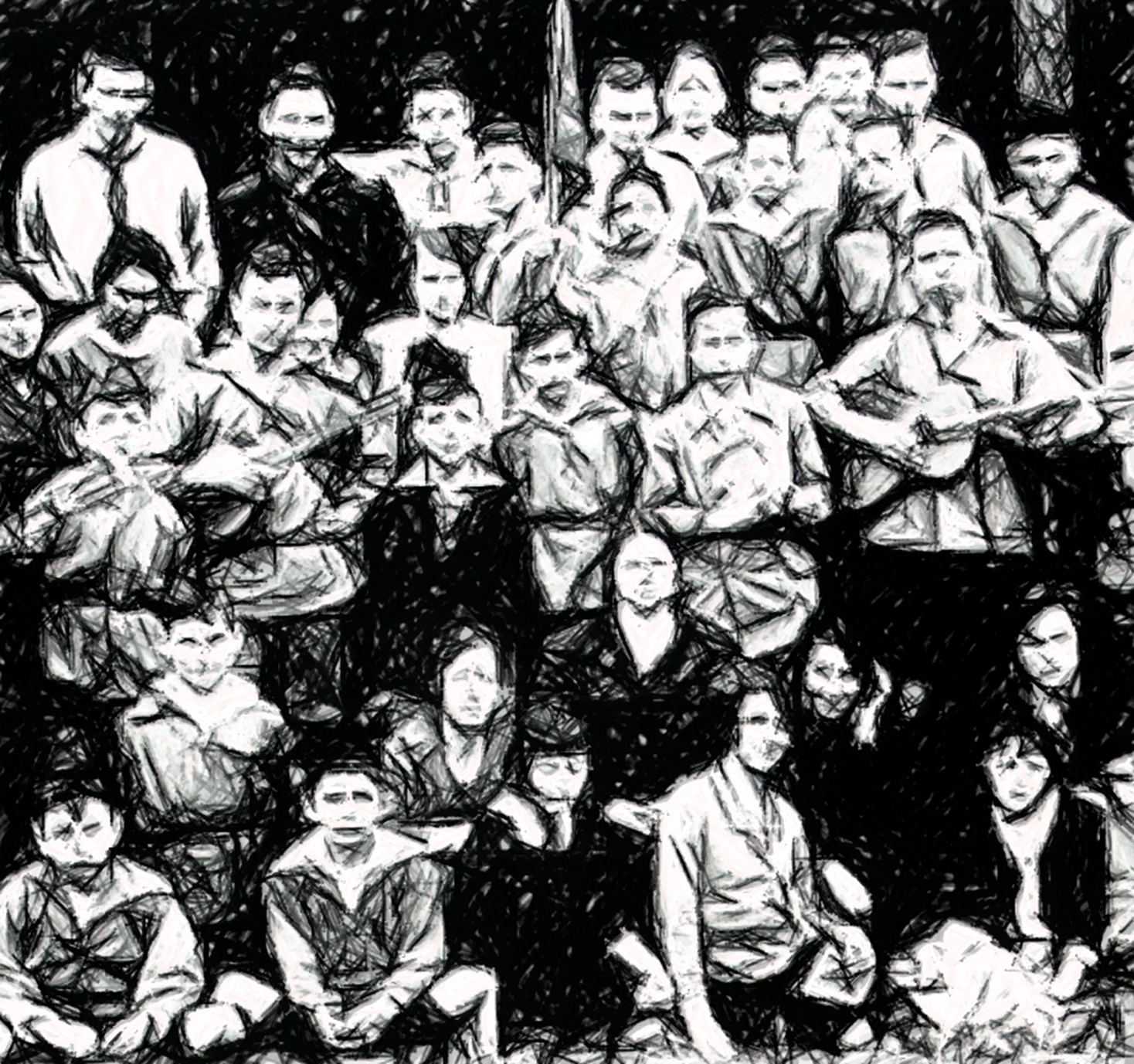
Aus dem Dunkel / Wie Juden aus Frankfurt/Oder den Nazis entkamen
In Frankfurt/Oder gab es 1933 etwa 800 Mitglieder der jüdischen Gemeinschaft. Die meisten von ihnen verloren in den folgenden Jahren unter ständig zunehmenden Demütigungen zuerst ihre Rechte, dann ihre Existenzgrundlage, ihre Freiheit, schließlich ihr Leben. Das Problem war nicht, aus Deutschland herauszukommen. Es war Ende der 1930er Jahre für jüdische Emigranten schier unmöglich, in irgendein anderes Land hineinzukommen.
Einigen gelang es dennoch, allen Widrigkeiten zum Trotz, unter teils abenteuerlichen Umständen. Die Flucht führte sie nach Palästina, Südamerika, den USA, Afrika, Australien oder China. Dem Tod knapp entronnen, waren sie mit neuen Herausforderungen konfrontiert. In der Fremde mussten sie neue, ungewohnte Lebenswege meistern, als Soldat, Farmer, Hausdiener, Plantagenarbeiter oder Spion. Dieses Buch basiert auf den Erzählungen der jüdischen Überlebenden von Frankfurt/Oder, von ihrer Flucht und ihrem Neuanfang.
[ Leseprobe ] [ Taschenbuch ] [ Ebook ]
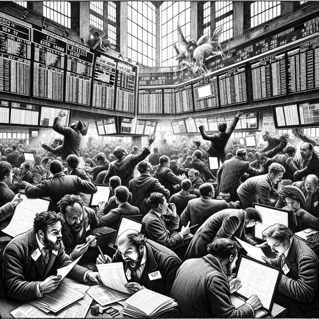
Das Schwarze Börsenhackerbuch / The Black Book of Financial Hacking
Der Traum jedes Traders: Mit einem kühlen Bier am Strand sitzen, während der Computer für Sie an der Börse handelt und Ihr Konto wachsen lässt. Kann das tatsächlich funktionieren? Kommt darauf an.
Dieses Buch vermittelt die Grundlagen für Entwurf und Test mechanischer Handelssysteme. Nicht mit “technischen Indikatoren”, sondern auf solider mathematischer Grundlage. Sie lernen, wie man Handelssysteme zusammenbaut, wie man sie richtig testet, unter welchen Bedingungen sie funktionieren und wann sie versagen. Zur Anleitung dienen Beispielsysteme mit neuen Methoden, wie Spektralanalyse, statistischen Filtern und künstlicher Intelligenz. Alle beschriebenen Systeme sind in der Begleitsoftware zum Buch enthalten und können als Grundlage für eigene Systeme verwendet werden. Hacken Sie die Börse!